How To Wire A Start Stop Contactor
THREE PHASE MOTOR CONTROL CIRCUIT, EMERGENCY STOP - YouTube 0:00 / 3:48 THREE PHASE MOTOR CONTROL CIRCUIT, EMERGENCY STOP INDO TECH ELECTRICAL 11.4K subscribers Subscribe Subscribed 345.

Wiring Diagram Contactor And Overload
Emergency stop switches (also referred to as E-stop, kill switch, emergency off, and emergency power off) are used in applications where there is a need to shut down equipment or machinery quickly. These are often used in factories where machinery can cause damage to itself, things around it, or any human nearby if it starts to act in an.
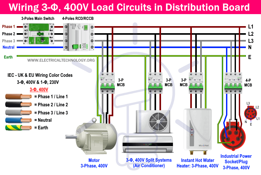
Three Phase Electrical Wiring Installation in Home NEC & IEC
Discuss Three Phase Emergency Stop Button in the Electrical Forum area at ElectriciansForums.net. 1; 2; Next. 1 of 2 Go to page. Go. Next Last. BigSi-Reaction score 55. Jun 15, 2015. Your E-stop would have to be integrated with the machine's existing controls and this will require an understanding of the present risks and how your mods will.
Three Phase Motor Control Circuit Diagram
119. Reaction score. 0. Country. 1 Sep 2007. #3. The best way would be to use a safety relay, try searching Farnell or RS components for one. If you interupt the coil of the contactor using the e-stop, you may have issues about automatic startup when the e-stop is reset. However one way of fixing this issue is by placing the e-stop in series.

Three Phase Motor Wiring Diagram Phase Motor Circuit Control Works Wiring A Single Phase
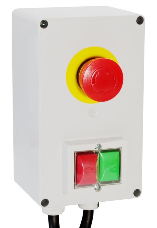
Control Panel Details: The compact control panels are made of durable ABS plastic and maintains a UL94 V-0 rating. The start and stop buttons are custom manufactured by OTTO Controls in Illinois and are designed for long-term durability with solid aluminum bezels, a no-slip surface finish, and a strong tactile response. The latching emergency-stop button is Swiss-manufactured by EAO.

Start Stop 3 Phase Motor Starter Wiring Electrical Engineering Updates
1 2 3 4 Next Canus Registered Registered Joined Mar 19, 2018 Messages 287 Feb 10, 2021 #1 Is there such a thing as an Emergency Stop Switch for a 3 phase device? I have a Southbend 16" lathe and would like to install an E stop switch on it. I would assume it would be a NC switch that will open when pressed. S sdelivery H-M Supporter - Gold Member

Basic Inverter fitted with an Estop button. 1 Phase input / 3 Phase output. Variables, Power
An E-Stop is a manually operated device, activated by a single human action, which is designed to open a circuit to one or more pieces of equipment without creating any additional hazards. This device must remain in its actuated (open) position until normal operation can be restored.
Threephase motorstarter 400 V with emergency stop button
Buy Emergency Stop Switches / E Stop. Newark offers fast quotes, same day shipping, fast delivery, wide inventory, datasheets & technical support.

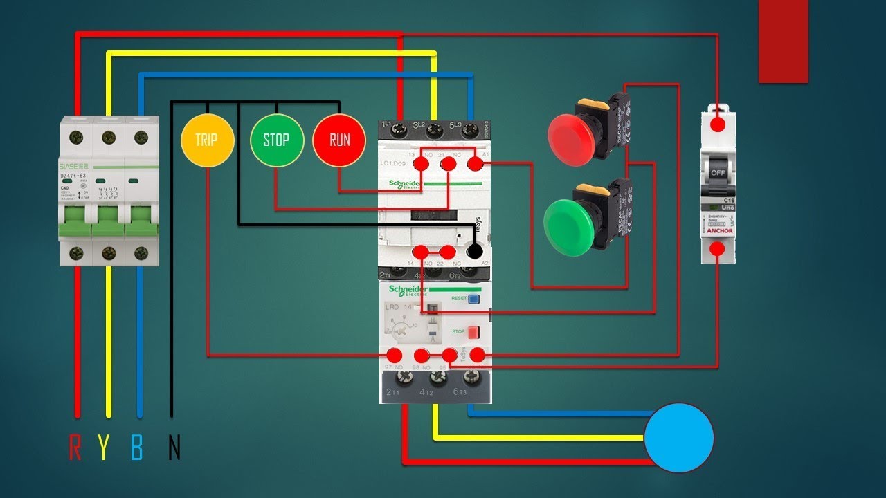
How To Wire A 3 Phase Contactor
Emergency Stop Device with 3-Pole Contacts (ES-P) The ES-P emergency stop button is used to immediately halt hazardous processes or machinery in order to prevent or minimize injury to personnel or damage to equipment. Body Material: High Specification Polyester in Yellow Ingress Protection: IP67 Contacts: 3NC or 2NC + 1NO
Wiring Diagram 3 Phase Motor
E-Stop Station - An enclosure assembly including the E-Stop button, which can be mounted onto any surface where an emergency off switch should be located. The three most common types of Emergency Stops are: Push-pull - the operator is pushed in and locks into stop; released by pulling back. Indicated by the circle symbol on the head.

e stop wiring diagram ZefhremAmani
1 2 3 4 5 » Emergency Stop Switches / E-Stop Switches are available at Mouser Electronics. Mouser offers inventory, pricing, & datasheets for Emergency Stop Switches / E-Stop Switches.
Three Phase Transformer Connections Phasor Diagrams Electrical Academia
Emergency stop buttons, also known as E-Stops or kill switches, are used to reduce the risk of injury by stopping machinery quickly. Emergency stop buttons are fitted for easy access in any emergency. E-Stops are red and must feature a yellow background, bezel, or housing for attention. The button is designed to be operated easily, even with.

240 Volt Contactor Wiring Diagram
With multiple ports, these switches maintain the air pressure of your electric air compressor, while also including ports for up to three air-powered devices, reducing the complexity of your air system setup. Choose from our selection of three-phase switches in a wide range of styles and sizes. In stock and ready to ship.
electrical Role of the neutral conductor in three phase systems Electrical Engineering Stack
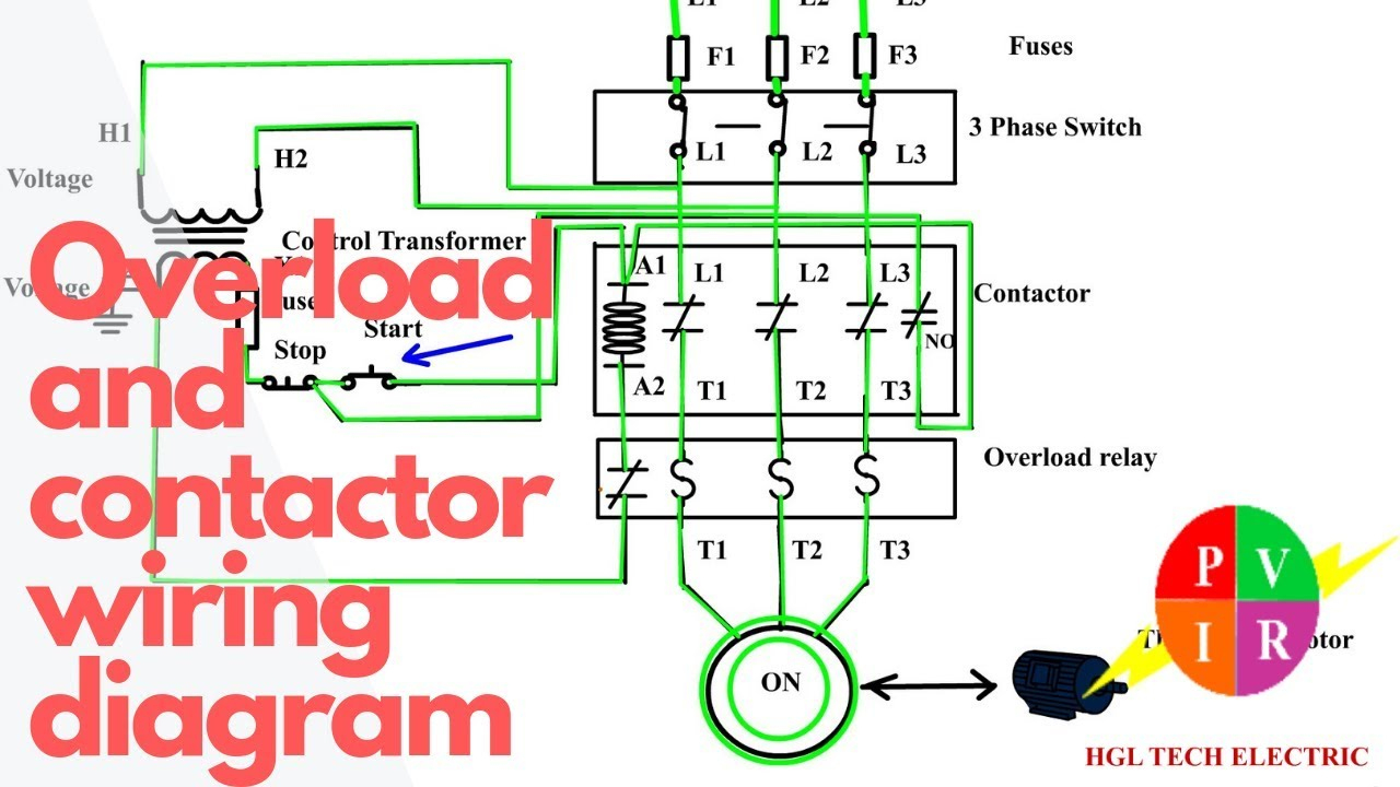
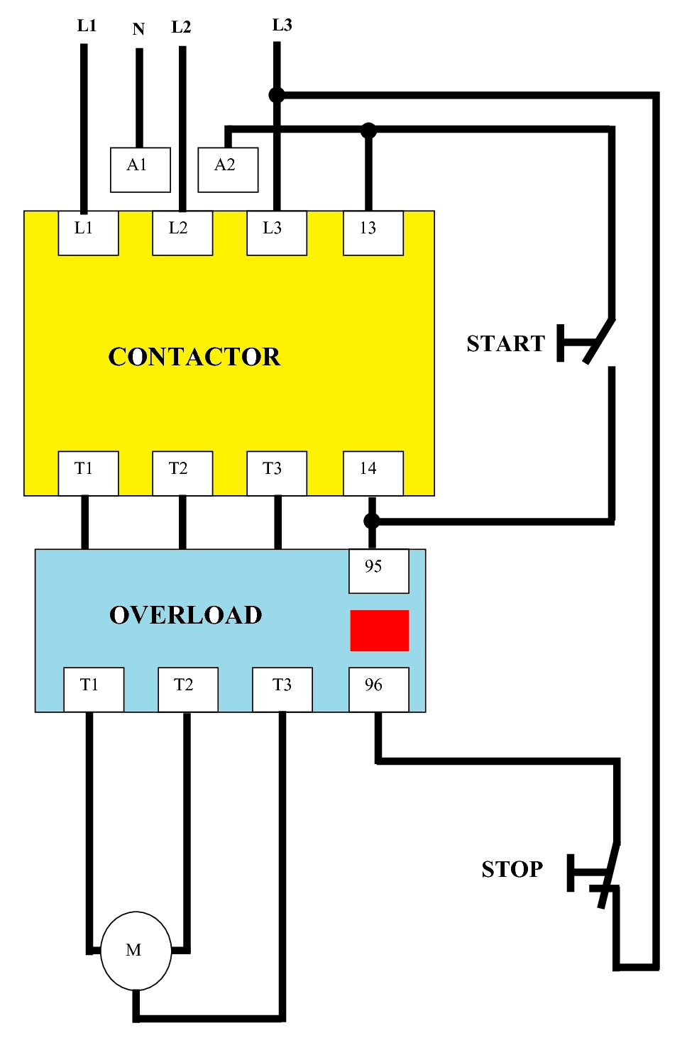
A Three-phase Contactor Four Terminal Emergency Stop Switch Start Push Button Switch Stop Push Button Switch A Buzzer At the far upper left of the diagram, you'll notice an arrow that says power supply. This is the main source of electricity for the entire circuit.
Motor Starter Diagram. Start Stop 3 Wire Control. Starting A Three 3 Phase Motor Starter
Switches Metal 22 mm Emergency Stop Panel-Mount Push-Button Switches Plastic 22 mm Emergency Stop Panel-Mount Push-Button Switches Vibration-Resistant Plastic 22 mm Emergency Stop Panel-Mount Push-Button Switches A single -piece construction prevents the contact block from separating from the actuator in high-vibration applications.
3 Phase Contactor Wiring Diagram Start Stop Pdf Wiring Harness Diagram
3- and 4-pole models Large 40mm operator Lid safety trip mechanism ensures the safety contacts will open if the lid is removed One tamper-proof T20 Torx bit included for stainless steel versions For part listings and specifications, go to Shop Now ES Series 3-Pole E-Stop Switches
