
3 Wire Fuel Gauge Wiring Diagram
Step 9. Once the level sending unit is installed, it needs to be connected to a gauge. The below wiring should be followed: 1) Connect ground (pink) wire from the KUS sending unit to a common grounding hook-up. 2) Connect (black) wire from the KUS sending unit to gauge hook-up. If your gauge has color coded hook-ups, maintain this coding as you.
12+ 3 wire fuel sending unit wiring diagram ListonBalqis
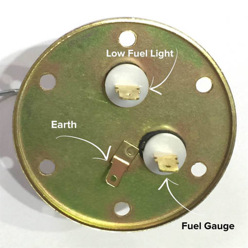
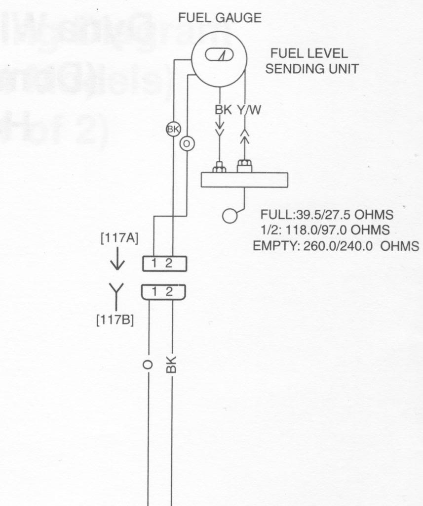
The wiring diagrams I have show a fuel gauge with two terminals, one for power and one for the sender.. The fuel sending unit wires are located on top of the gas tank where they are hard to get to without dropping the tank. The fuel sending unit should have a pink wire with voltage on the isolated center post. The other black wire on the.
3 wire fuel sending unit wiring diagram SatyaCampbell
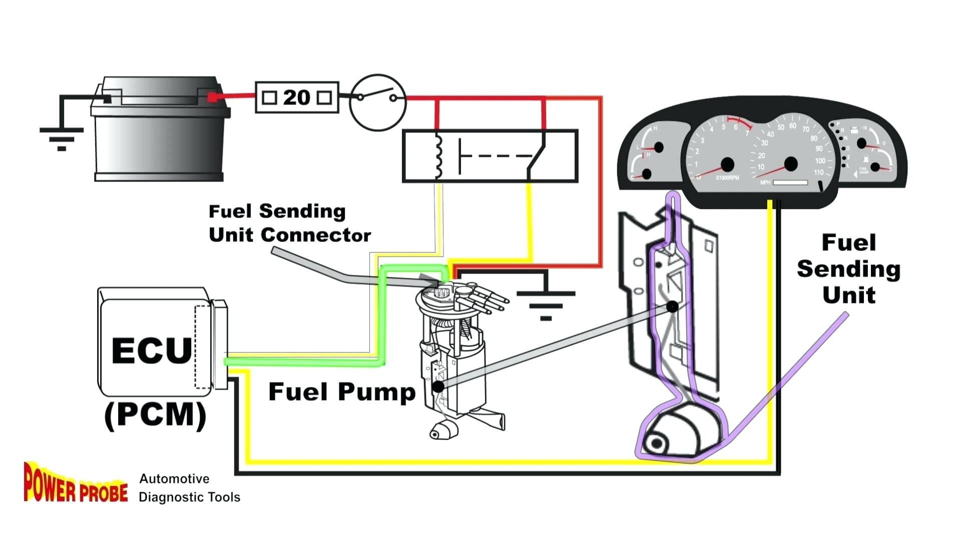
The 3 wire fuel sending unit wiring diagram consists of three main components: the fuel sending unit, the fuel gauge, and the wiring that connects them. The sending unit is located inside the fuel tank and contains a float that is attached to a variable resistor. As the fuel level in the tank rises or falls, the float and resistor move.
Sending Unit Wiring Diagram Organicic
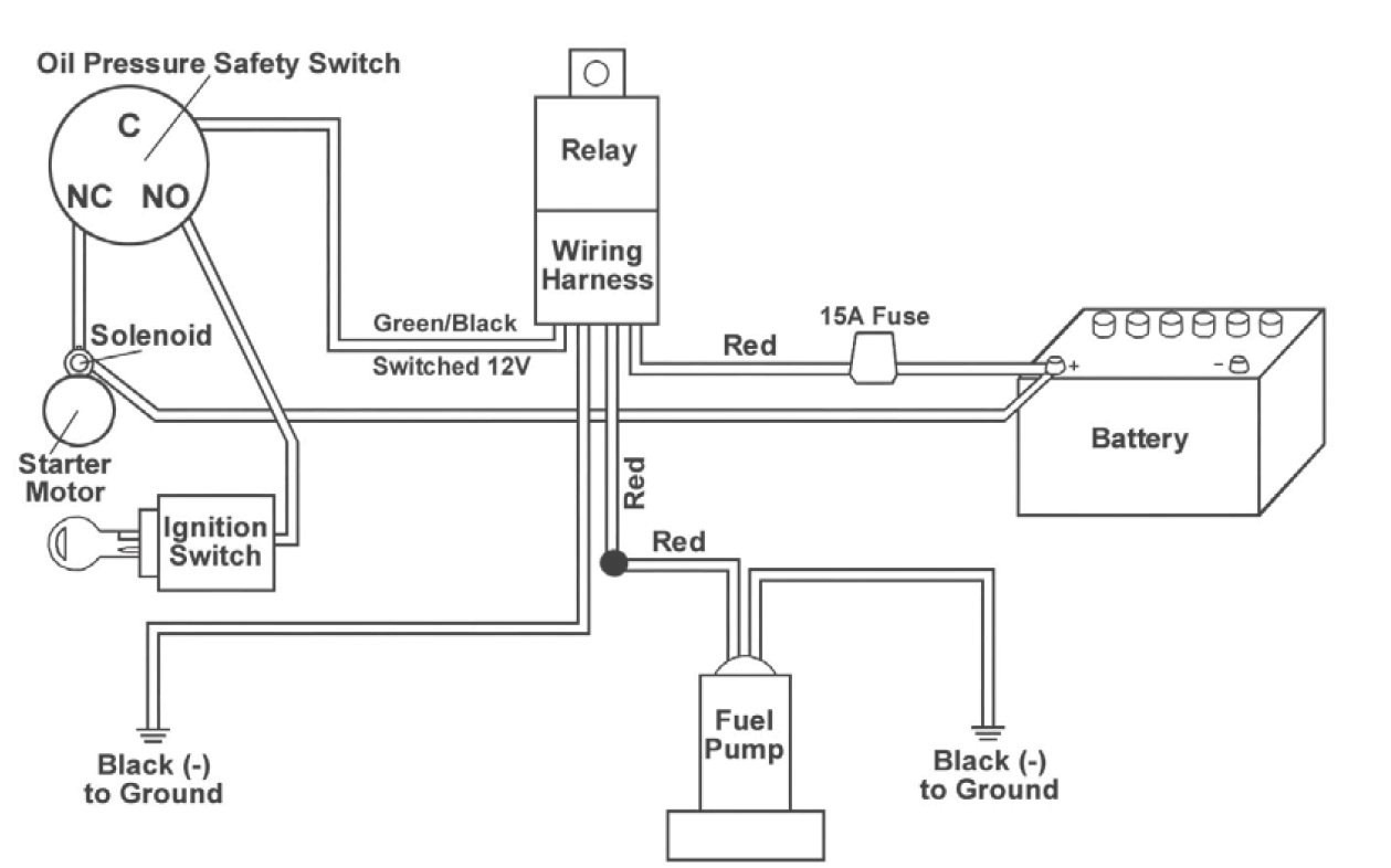
Gauge and Sending Unit Wiring Diagram and Industry Recommendations. IGNTION SWITCH BLACK BULB SENDER GRND SENDER BATTERY GROUND FUEL . Recommended Marine Wiring Color Code Direct Current Systems - Under 50 Volts (No diagram required if wiring is in compliance with Tables I and Il) Color Yellow w/Red Stripe (YR) Yellow (Y) Dark Gray (Gy) Brown (Br)
Wiring Diagram For Fuel Gauge On Boat Wiring Expert Group
Table of Contents. What Is a Fuel Sending Unit. How To Wire a Fuel-Sending Unit. Step 1: Locate the Fuel Sending Unit. Step 2: Test the Fuel Gauge. Step 3: Repairing Faulty Wiring. Step 4: Remove the Faulty Fuel Sending Unit. Step 5: Test the Old Fuel Sending Unit. Step 6: Install the New Fuel Sending Unit.

Sea Ray Boat Wiring Diagram General Wiring Diagram
An old-school approach to quickly diagnose your fuel sending unit and the gauge. Most times, the wiring is bad. Use this video as a reference.Heres a link to.
3 wire fuel sending unit wiring diagram BrookLalayne
Step 5. Run the other wire from the sending unit to the nearest ground connection. Connect the wire to the post using the same method used to connect the wire to the ignition switch, and insulate the connection. Reconnect the negative battery terminal. The fuel sending unit is responsible for what the fuel gauge on your vehicle reads.
12+ 3 wire fuel sending unit wiring diagram ListonBalqis
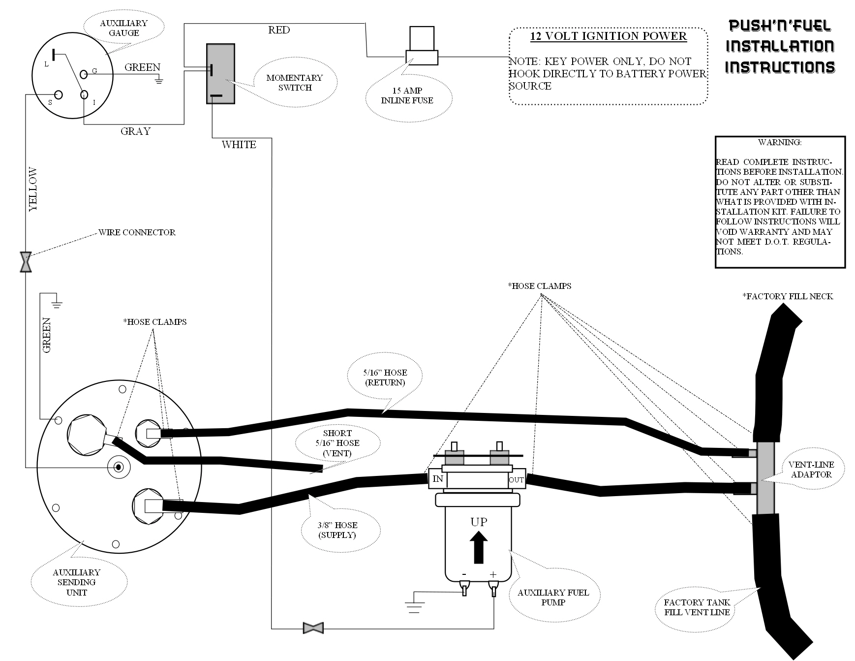
FUEL LEVEL SENDING UNIT INSTRUCTIONS PARTS LIST I SENDING UNIT 1 RETAINING RING GASKET 5 10x24x1-1/4" BOLTS 5 WASHERS ÞOLTS W/ WA5HEK5 SENDING UNIT GÁ5KET TAIN!NG Unbolt cap assembly and remove foam from cell. TOOLS REQUIRED. Attach wire from gauge to terminal marked S, and ground wire to the terminal marked G..
Fuel Sending Unit Wiring
Fuel sender unit wiring and tubes. My wiring diagram shows three wires at my fuel gauge. Power, ground, and pink circuit 30 running to the fuel tank's sender unit. All three are shown running to a rectangle of boxes with circuit numbers in the boxes. one wire runs to directly to metal on the inside of the cab (ground I assume);
3 wire fuel sending unit The Hull Truth Boating and Fishing Forum
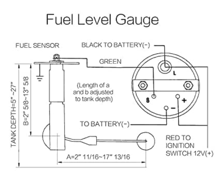
SHORT SWEEP ELECTRIC FUEL LEVEL GAUGE 2650-1858-77 Wiring: Sending Unit Wiring: Gauge Mounting: Gauge to Sender Compatibility: Looking at the rear of the gauge, you will have 3 terminals labeled S, I, & GND. You may use 18g or 20g stranded wire for all fuel level gauge wiring. S = This connects to the sending unit in the fuel tank. **(See.
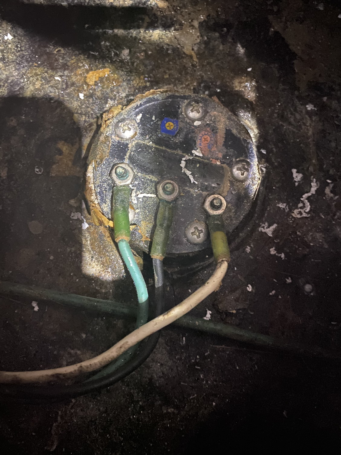
Fuel sending unit wires DSMtuners
The 1989 4.2L engine wiring diagram does not have any relays in it. My battery has two relays mounted next to it, and according to the 2.5L wiring diagram that's the fuel pump and latch relay. There is an orange wire going to one of them which would be the fuel pump output wire. it's hard to see where else the orange wire goes to.
RyseTormod
A 3 wire fuel gauge wiring diagram is a helpful guide to properly wiring your fuel gauge. The diagram will show the power wire, ground wire, and the signal wire, as well as the connections to the fuel sending unit. The diagram will also show the color codes for the wires, which is important to ensure the proper connections are made.
1989 RS Camaro Fuel Gauge wiring confusion Third Generation FBody
soapy water around the seal. (see Figure 3)-IMPORTANT: IF UNSURE OF THIS OR ANY OF THE DETAILED PROCEDURES, SEEK PROFESSIONAL ASSISTANCE. PROPER WIRING INSTALLATION: -Connect ground (pink) wire. from the KUS sending unit to a common grounding hook-up.-Connect (black) wire. from the KUS sending unit to gauge hook-up.

1995 chevy silverado fuel pump wiring diagram Wiring Diagram and
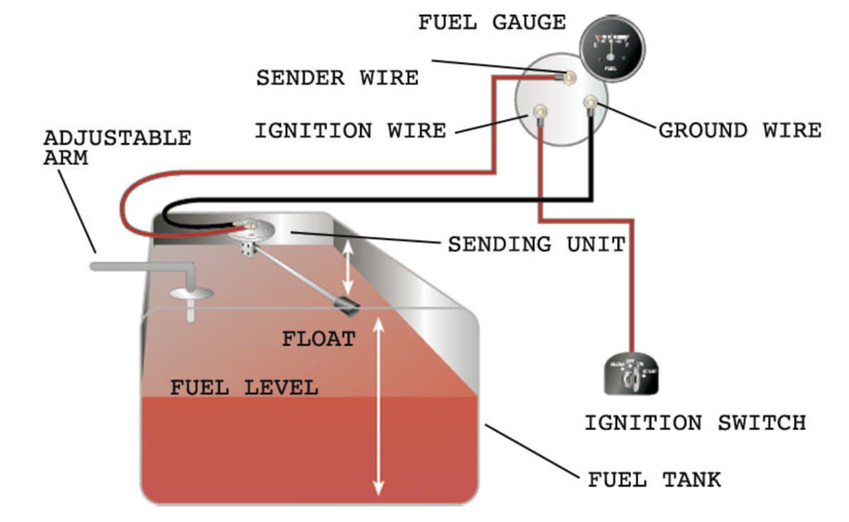
First, find a suitable location for a new fuel gauge. Then, identify the four wires that are connected to the fuel gauge. Ground the wire by using the car's metal surface. Figure out the power-carrying wire from the fuse box and connect the + wire to it. Connect the S wire to the fuel pump sending unit.
3 wire fuel sending unit wiring diagram SatyaCampbell
The fuel gauge wire never comes out from under the dash. It goes from the control switch up to the back of the gauge cluster. The early models that had dual tanks did the electrical switching for fuel reading at the switch unlike later models such as mine that switched electrically at the selector valve.
fuel gauge wiring confusing Page 2 Harley Davidson Forums
This video will help you troubleshoot your fuel gauge and sending unit, to verify if it is good or needs to be replaced.
