🔎 USB > RJ45 Tout savoir
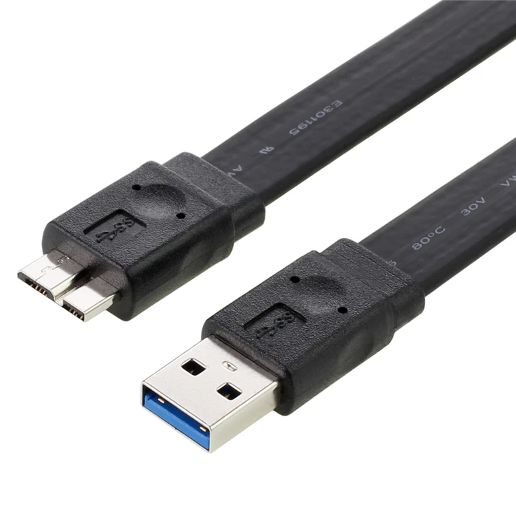
Who knows what the future reserves? USB Connections Each USB device uses the standard A type connector to the USB host or Hub through A type receptacle. The other end of the cable has series B connector which is used to plug into the B type receptacle.
Wiring Diagram Of Usb Cable Wiring Diagram Schemas
USB-A. USB-A, or USB Type A, is the original flat and rectangular connector that no one could ever figure out how to plug in correctly the first time. These cables always have USB-A on one end with a different port type on the other, and can be used for device charging and data transfer. USB-A is still widely used and can be found on devices.

Usb Wiring Diagram Computer
Description: USB wiring is simple but not that simple this is because on changing the frame of reference the pinout looks changed. It can be noticed that pin-out the front side be different than that of back side and thus it requires to check the connectivity of both ends with a digital multi-meter (above micro USB pinout made it simple for you).

Micro Usb Power Schematic Wiring Diagram Schemas
I make USB cables (USB-A to Mini or Micro primarily), but don't have any experience with USB-C. I would like to create a cable that has a USB-A (2.0) connector on one end, and a USB-C connector on the other (mainly for connecting keyboards to CPUs, and charging devices). How do I wire this properly (typically I use a 4-core 28AGW cable)?
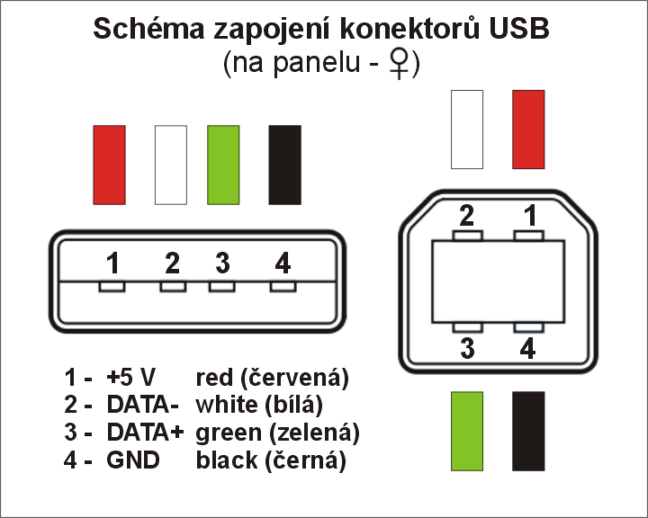
Připojovací konektor USB. Pájecí schéma
download putty. After downloading and installing Putty, connect the FTDI cable with your computer. Open the device manager and find the name of the COM pin in the ports list. Note down this port name, we will need it, later on, to connect Putty with USB to the serial converter device.
Schaltplan Usb Steckdose
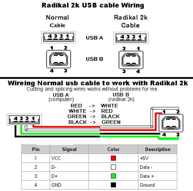
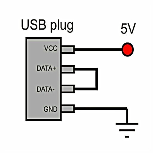
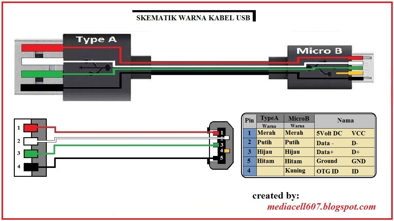
Step 2: Wires and Soldering. - Peal the ends of your wires and put a small amount of solder on so you can solder them on connector more easily. - Here is a simple schematic of a USB cable which shows you the correct order of the pins and the default color of each pin. - Standard USB connector has 4 pins.
Wiring Diagram Of Usb Cable Wiring Diagram Schemas
01 [Quick View ]What is a USB? The Colors of the USB Wire 02 Learn Some USB Wiring Diagrams 03 Use EdrawMax for Wiring Diagram Creation [Free to Use] 04 Bonus Tips: How does the USB Work? What is a USB? Today, almost all the devices connected to the PC are USB-driven. Devices like mouse, keyboard, printer all require a USB cable to operate.

Usb Mini B 5 Pin Wiring Diagram Wiring Diagram Schemas
USB cable schematic. 01 Mar 1998. serial interface cable Very simple. Maximum length of cable is about 5 m. 4 pin USB A / USB B / mini-USB jack connector. 4 pin USB A or USB B plug connector. Pin one side. Signal.
🔎 USB ¡ Conócelo todo
Very simple. Maximum length of cable is about 5 m for AWG20 and 0.8 m for AWG28 cable. USB D+ and D- are twisted in cable. Outer shell is made of copper braid and aluminum shield. Colors do not mean anything in the wiring scheme. You can use any color wire to rig something. Just make sure the colors match from end to end.
Schema Kabel Usb Rs232
USB type-c details. Developed at roughly the same time as the USB 3.1 specification, but distinct from it, the USB Type-C Specification 1.0 defines a new small reversible-plug connector for USB devices. The Type-C plug connects to both hosts and devices, replacing various Type-B and Type-A connectors and cables with a standard meant to be future-proof, similar to Apple Lightning and Thunderbolt.
Usb Mini B Cable Wiring Diagram Wiring Diagram
USB C cable wiring diagram. This article mainly introduces the USB C cable wiring diagram, the pin definition of the 24Pin USB Type C interface and how to connect the core wires, as a reference for hardware design. Let's first understand the pin definition of 24Pin USB C. Female. Male. For the USB C cable, we mainly introduce the male connector.
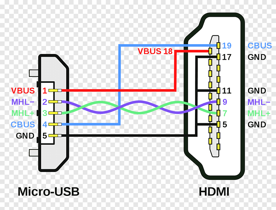
Diagrama USB ¡Descarga & Ayuda 2021!
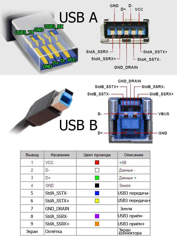
1. USB 2.0 Pinbelegung 1.1. USB 2.0: Pinout USB-A & USB-B 1.2. USB 2.0: Pinout Micro- & Mini-USB 2. USB 3.0 Pinbelegung 2.1. USB 3.0 Pinout: USB-3.0-A, USB-3.0-B (-Powered) &.
Skema Kabel Usb Skema Diagram
Bei den Steckern bzw. Buchsen unterscheidet man zwischen Downstream und Upstream. Für den Downstream, also die Richtung vom Host zum Hub, wird das USB-Kabel über die Stecker-Buchse-Kombination Typ A angeschlossen. Für den Upstream, also die Richtung zum Host, wird das USB-Kabel über die Stecker-Buchse-Kombination Typ B angeschlossen.
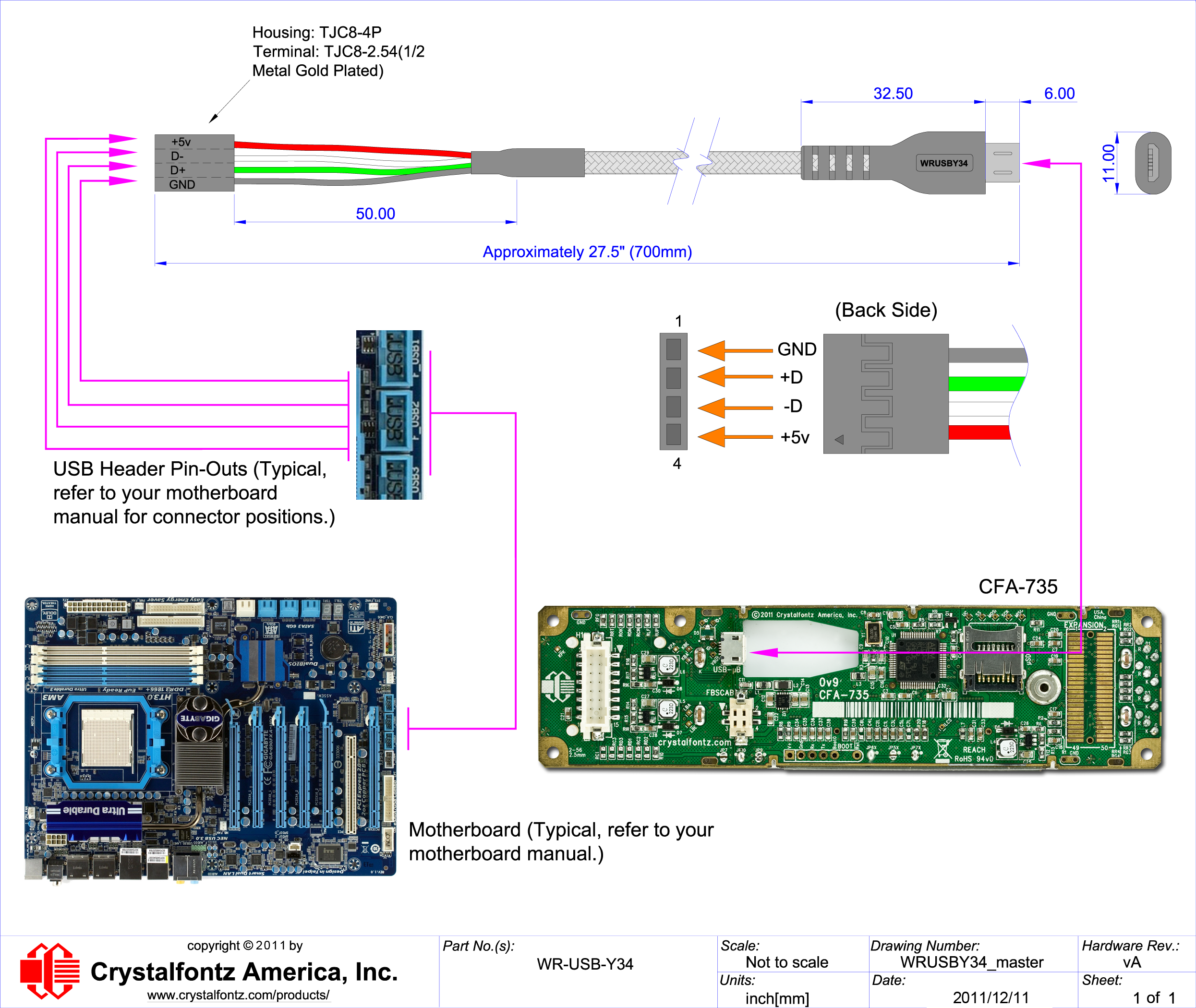
Micro USB to 4Pin Cable from Crystalfontz
USB Type-C ® Cable and Connector Specification With the continued success of the USB interface, there exists a need to adapt USB technology to serve newer computing platforms and devices as they trend toward smaller, thinner and lighter form-factors.
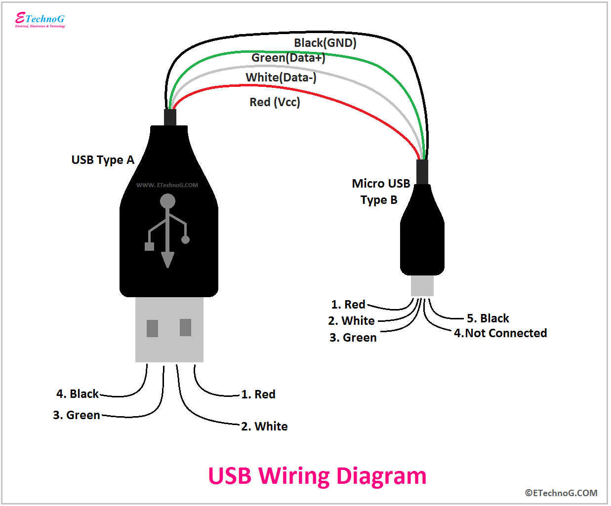
USB Wiring Diagram, Connection, PinOut, Terminals ETechnoG
Generally, you can successfully use Thunderbolt cables for a USB-C power and SuperSpeed data connection, but longer "active" thunderbolt cables (over .5 meters) will be slow, falling back to only 480Mbps. Like standard USB-C cables they can charge at 3A/60W, some up to 5A/100W. Going the other way, USB-C cables rated for "SuperSpeed" of any
ps2 to usb schematic
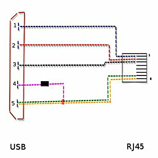
AP9827 cable for CS500 ------------ RJxx end (looking AGAINST the connector,numbering reversed): ------ | -- 1 - green - USB 3 - USB+ | -- 2 - white - USB 2 - USB- | -- 3 _| -- 4 - black - usb 4 - GND | | -- 5 |_| -- 6 | -- 7 - brown - shield | -- 8 | -- 9 | -- 10 - red - usb 1 - +5V ------ USB end (looking against the connector): --.
