Atx Power Supply Circuit Diagram Pdf Wiring Diagram
What is a Boost Converter? To be clear, the other common use of the boost converter is for AC to DC power supplies for power factor correction and that requires a complete and separate treatment. When I say DC to DC, I mean converters with an input voltage that is positive and does not move up and down quickly.
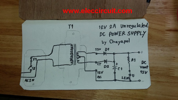
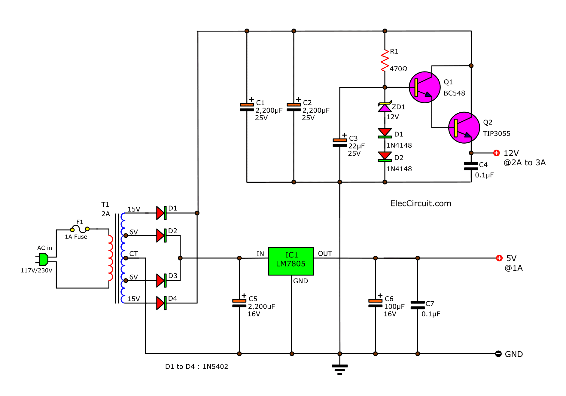
Simple 12V 2A Power supply circuit
For successful circuit-building exercises, follow these steps: Carefully measure and record all component values prior to circuit construction, choosing resistor values high enough to make damage to any active components unlikely. Draw the schematic diagram for the circuit to be analyzed.
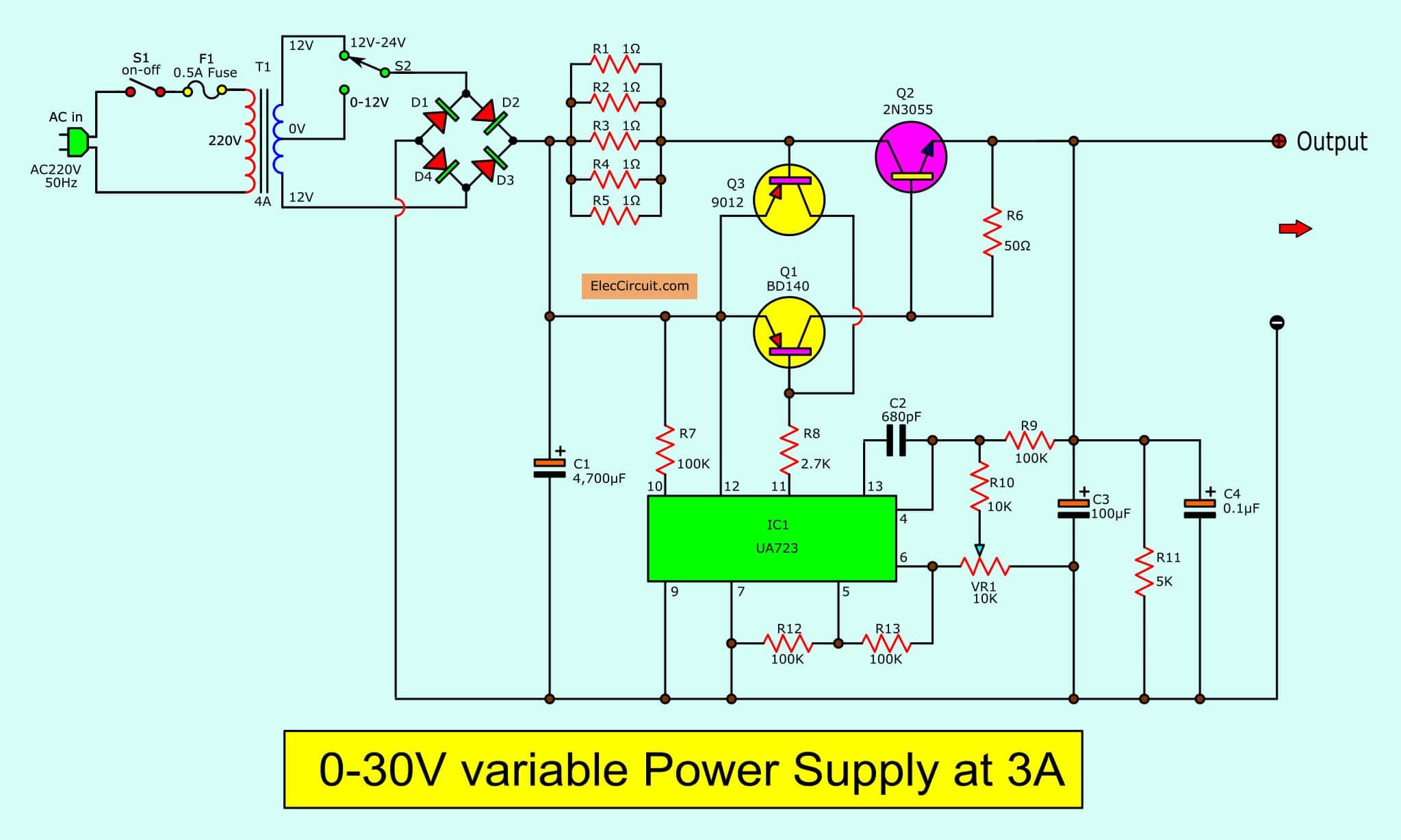
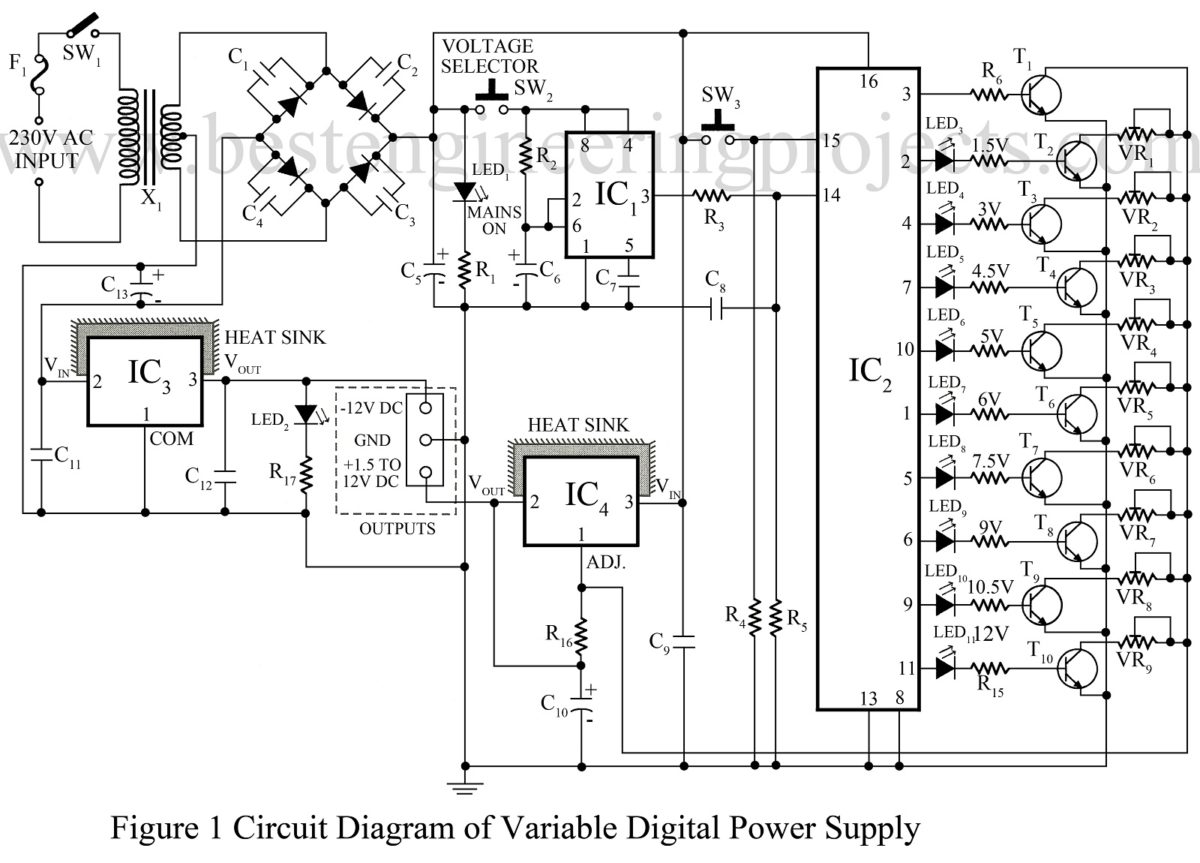
030V Variable Power Supply circuit Diagram at 3A
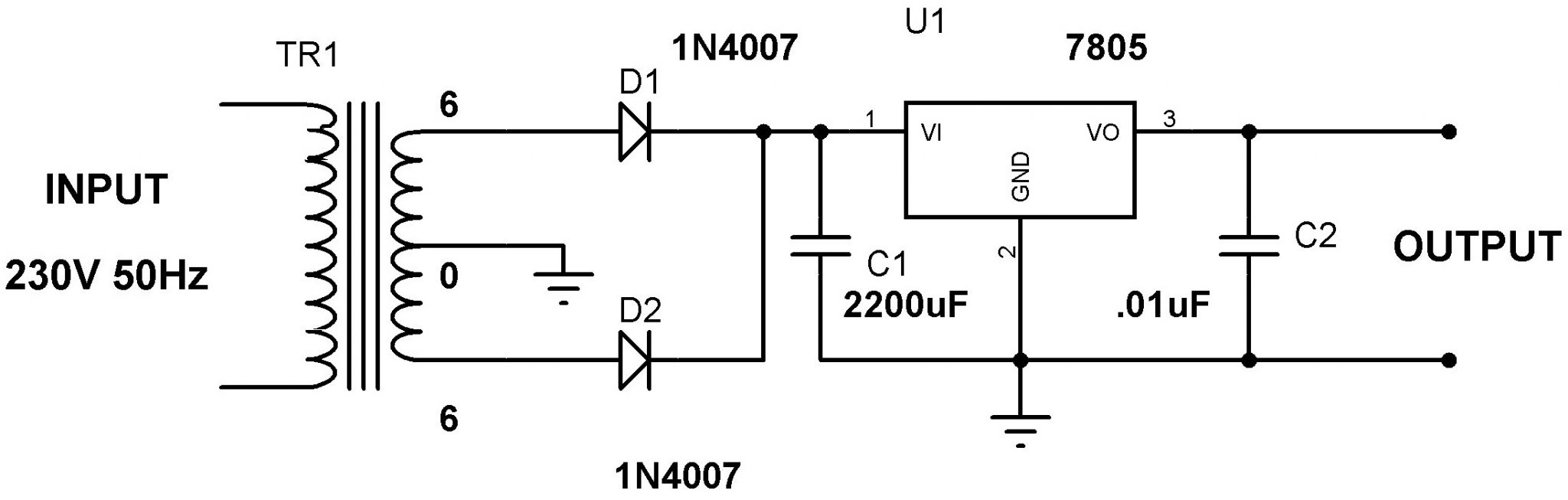
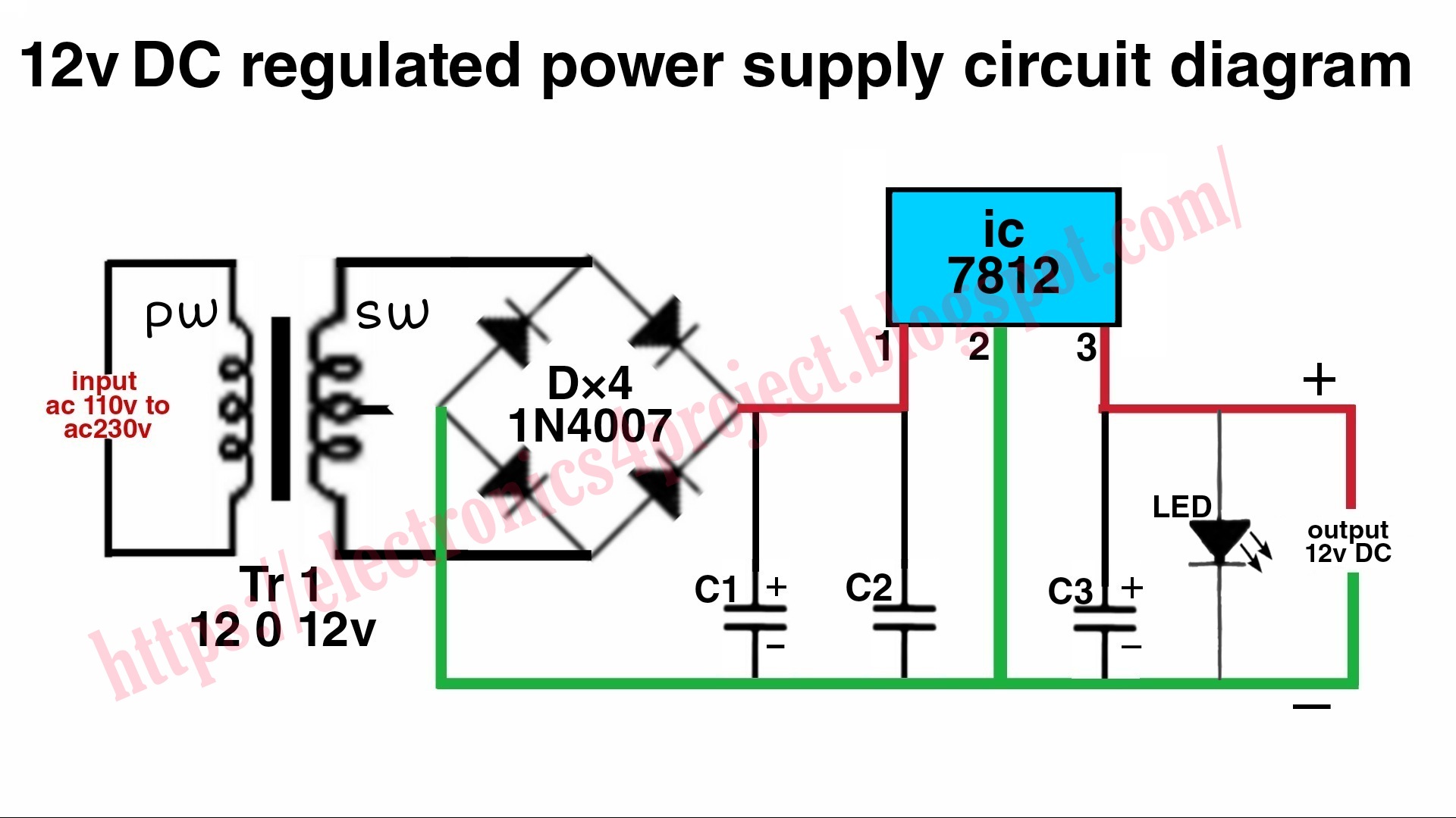
Step 4: Regulate the DC voltage. At this point, the output voltage of the 1000 uF capacitor is 9 V DC. To regulate the voltage to 5 V this example uses the LM7805 regulator. The LM7805 datasheet recommends placing two ceramic capacitors at the input and output terminals of 0.33uF and 0.1uF respectively. Also, you can see how a green LED was.

12 Volt 10 Ampere DC Power Supply Circuit
Figure 1. Buck converter topology. Figure 2. Simple boost converter. Figure 3. Inverting topology. Figure 4. Transformer flyback topology. Why Use a Switching Regulator? Switching regulators offer three main advantages compared to linear regulators. First, switching efficiency can be much better.
10+ Power Supply Schematic Robhosking Diagram
12V to 9V Converter 12V To 8V Converter Using LM7808 Regulator IC 9V Or 12V To 6V Converter Using LM7806 IC 12V to 5V Converter DC Voltage Doubler / Multiplier Circuit Adjustable Power Supply Using 7805 12V Power Supply Circuit 24V DC Power Supply Using LM7824 IC Circuit Diagram About Contact

Circuit Diagram of Regulated Power Supply with Component Rating ETechnoG
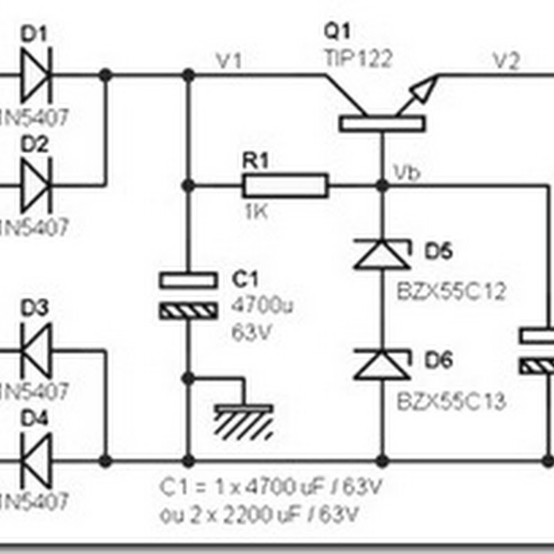
The main function of the regulated power supply is to convert an unregulated alternating current (AC) to a steady direct current (DC). The RPS is used to confirm that if the input changes then the output will be stable. This power supply is also called a linear power supply, and this will allow an AC input as well as provides steady DC output.
1V27V 3A Variable DC Power Supply Circuit Diagram Power Supply Circuits
The dc power supply converts the standard AC voltage available at wall outlets into a constant dc voltage. The dc power supply is one of the most common circuits you will find, so it is important to understand how it works.
12 Volt Dc Power Supply Circuit Diagram
A DC power supply schematic is a drawing of how the current flows through an electrical circuit from the source of DC power to the load in order to power an electronic device. Understanding these diagrams can be difficult, but with the right guidance and knowledge, anyone can get a grasp of how these diagrams work.
12 Volt Dc Regulated Power Supply Circuit Diagram
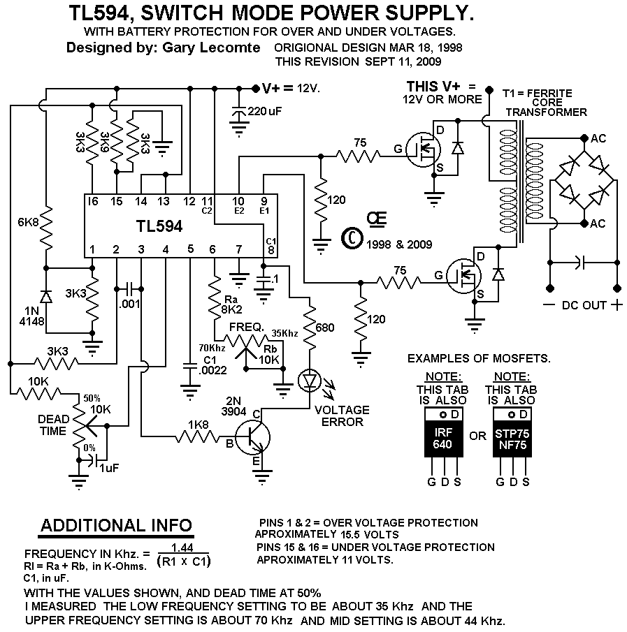
Top 8 power supply circuits Other Linear Power Supply Circuit Diagram Fixed Volts regulator: Adjustable Power Supply Circuit Switching Mode Power Supply circuits Switching Mode regulator DC to DC converter Related Posts 3 Power Source for Electronic Devices Let's look at the three most used types of Power Supplies. Types 1# Battery
24 volt dc power supply circuit diagram schematic
A simple circuit contains the minimum amount of components that allow it to be a functional electric circuit: a voltage source ε (battery), a resistor R , and a loop of wires for current I to flow around (see Figure 6 below). We usually ignore any resistance from the wires. Figure 6. Simple circuit diagram.
Circuit Diagram Of Power Supply
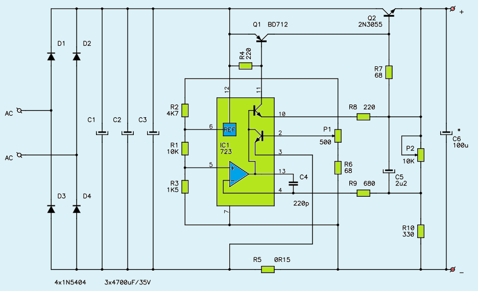
0-28V, 6-8A Power Supply Circuit Diagram using LM317 and 2N3055 This design can produce a current of 20 amps with little modification (use proper rating transformer and a huge heat sink with fan). Huge heat sink is required in this circuit, as 2N3055 transistors produce large amount of heat at full load. Circuit Components

12 Volt DC Power Supply Circuit
AC Plug - The first part of the circuit is the AC plug. When we create a DC power supply, it creates DC voltage from the AC mains voltage from a wall outlet. To build a DC power supply, purchase a 3-prong AC plug. It can also work with a two-prong AC plug. But having a 3-prong plug is better because ground provides better against possible.

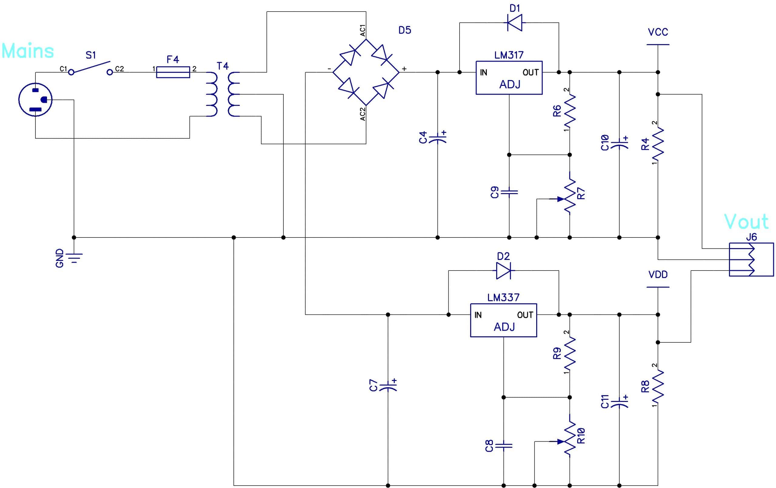
If you want a Dual Variable power supply circuit that covers the most appliances. This circuit
What is a rectifier in general? Rectifier is a device which converts the sinusoidal ac voltage into either positive or negative pulsating dc. P-N junction diode, which conducts when forward biased and practically does not conduct when reverse biased, can be used for rectification i.e. for conversion of ac into dc.
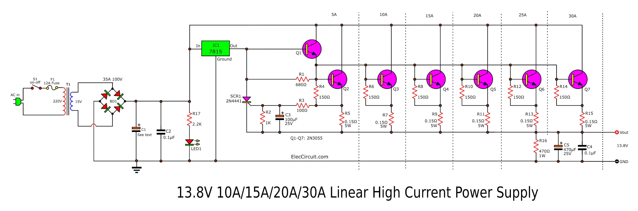
High Current 12V13.8V at 30A,25A,20A,15A Power Supply Elec Circuit
A DC voltage is a voltage that produces, or would produce, DC current, and an AC voltage produces or would produce AC current—and this introduces another terminology problem. "DC" and "AC" are sometimes attached to the word "current," even though these phrases mean "direct-current current" and "alternating-current current."
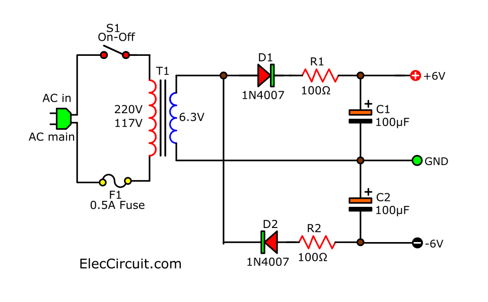
Basic Dual DC Power Supply 6V Electronic projects circuits
Advantages & Disadvantages of DC-to-DC Converters Advantages • It simplifies the power supply systems in the circuit. • It provides isolation in the primary and secondary circuits from each other. • It provides a technique to extend potential (voltage) as required. • It is available as a hybrid circuit with all elements in a single chip.
V Ac Power Supply Wiring Diagram vascovilarinho
A DC to DC converter is a power electronics circuit that efficiently converts a direct current from one voltage to another voltage. Without a doubt, DC-DC converters play an integral role in modern electronics. This is because they offer several advantages over linear voltage regulators.
