
Williams Wall Furnace Wiring Diagram Electric
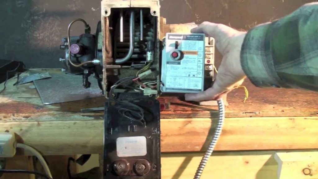
This one covers how to wire a replacement cad cell relay for the oil furnace. This video is part of the heating and cooling series of training videos made t.
29 Beckett Burner Parts Diagram Wiring Diagram List
Wiring diagrams comprise certain things: symbols that represent the ingredients inside the circuit, and lines that represent the connections between them. Therefore, from wiring diagrams, you realize the relative location of the ingredients and the way these are connected.
Beckett Oil Furnace Wiring Diagram Gallery Wiring Diagram Sample
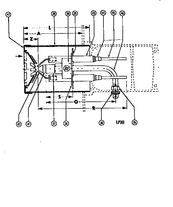
The volume of the furnace also infl uences the combustion process. R. W. Beckett Corp. recommends at least 1 cubic foot of furnace volume for each 150,000 BTU/Hr of fi ring rate. Figure 3. Maximum Capacity (at 3% O. Page 8 Section: Pre-installation Checklist Figure 5. Burner Dimensions Burner Model 10.1 - 10.3, 10.1S - 10.3S 10.4 - 10.6, 10.

Beckett Oil Furnace Wiring Diagram Free Wiring Diagram
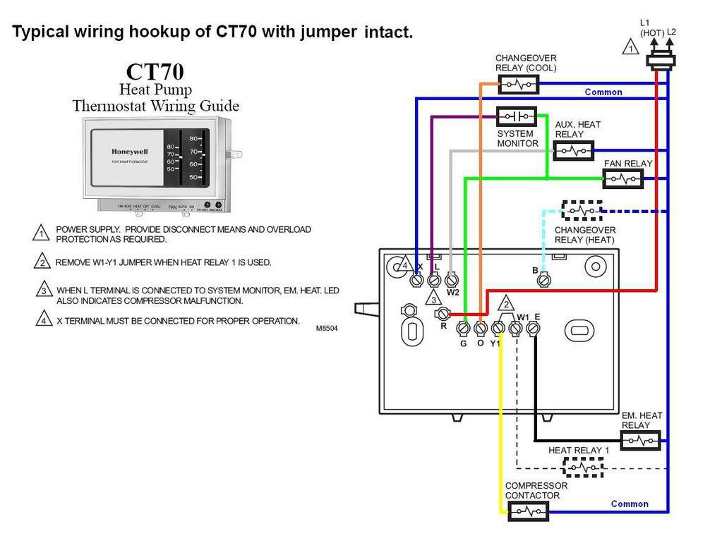
Here's what you need to know about oil burner thermostat wiring. The first step in wiring an oil burner thermostat is to connect the wires that lead to the furnace. You'll need to run a wire from the furnace to the thermostat, as well as between the thermostat and a power source, such as a wall outlet. Once you've connected the wires to.

Beckett Oil Furnace Wiring Diagram
Slide the nozzle line forward or back until this dimension is 1-3⁄8" for L1 & L2 heads if the tube has a straight shroud, or 1-3⁄4" if the air tube has a conic shroud. Tighten the hex head screw to secure the escutcheon plate to the burner chassis. Then tighten the splined nut and attach the oil connector tube. 3.
Beckett Oil Furnace Wiring Diagram Gallery Wiring Diagram Sample
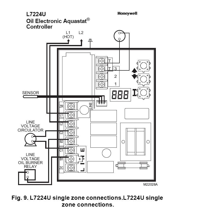
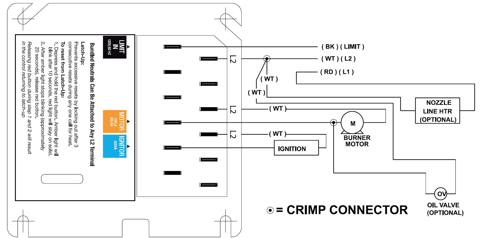
The Beckett GeniSys® 7505 Oil Burner Control is a 120 VAC primary safety control for residential and light commercial oil burners used in boiler, furnace, and water heater applications. The GeniSys® 7505 is used with the GeniSys® CAD Cell Flame Detector Kit 7006U to control the oil burner's motor, igniter, and optional solenoid valve.
Oil Furnace Wiring Diagram Wiring Diagram
Description / Applications The Beckett GeniSys TM Advanced Burner Control is a 120 Vac primary safety control for residential and light commercial oil burners used in boiler, furnace, and water heater applications having fi ring rates less than 20 GPH. The GeniSys is used with a suitable cad cell

12V Beckett Burner Wiring Diagram Easy Wiring
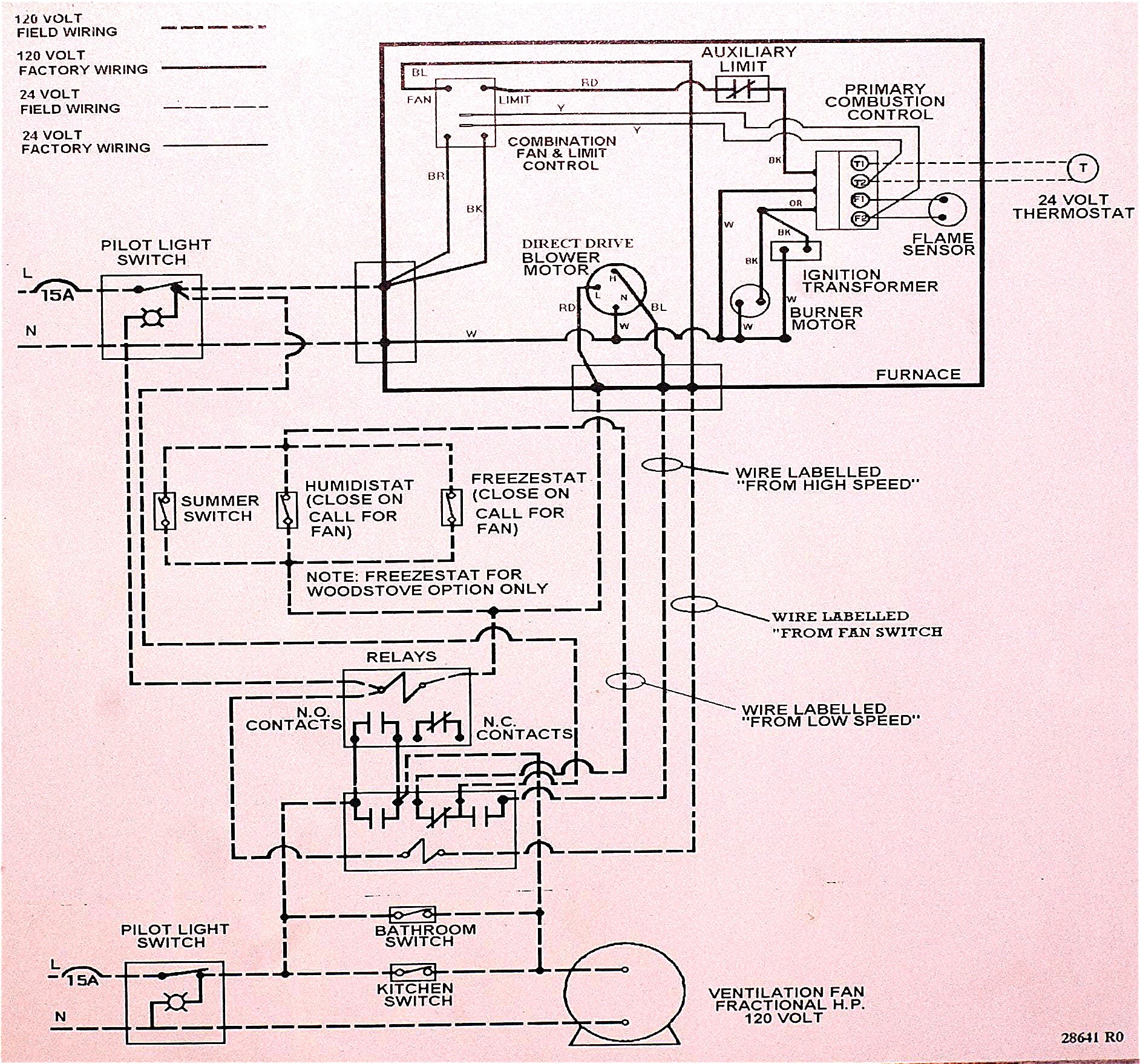
A wiring diagram for an oil furnace is a drawing that identifies each component of the furnace, its location, and the connections between them. It is important to note that all components of the furnace need to be connected properly in order for the furnace to operate efficiently and safely.

Beckett Oil Burner Wiring Diagram General Wiring Diagram
The Beckett oil 12 VDC igniter is designed to mount in the same manner as standard ignition transformers and igniters. 11.This igniter can be adapted to multiple base plates to accommodate Beckett ADC & SDC burners. CAUTION! Do not use this igniter beyond its design specifications. Improper operation and igniter failure may result.
[DIAGRAM] Gas Burner Diagram
Oil Burner . AFG Oil Burner Burner pdf manual download. Also for: Afg. Water, Oil Boiler wiring Addendum. Wiring Diagrams and Component Coding. Standard wiring for an oil boiler utilizing a Beckett Burner with Primary control. Your Beckett burner will provide years of .
Coleman Evcon Wiring Diagram
Burner Beckett af Instruction Manual. Oil burner (8 pages) Burner Beckett 120 Vac/60 Hz Instruction Manual. Oil burner (12 pages) Burner Beckett AFG Oil Burner Instruction Manual. Oil burner (12 pages) Burner Beckett AFII 100 Manual. Afii burner with type 'hlx' air tube (16 pages) Burner Beckett AFII 85 Manual.
Beckett Oil Furnace Wiring Diagram Gallery Wiring Diagram Sample
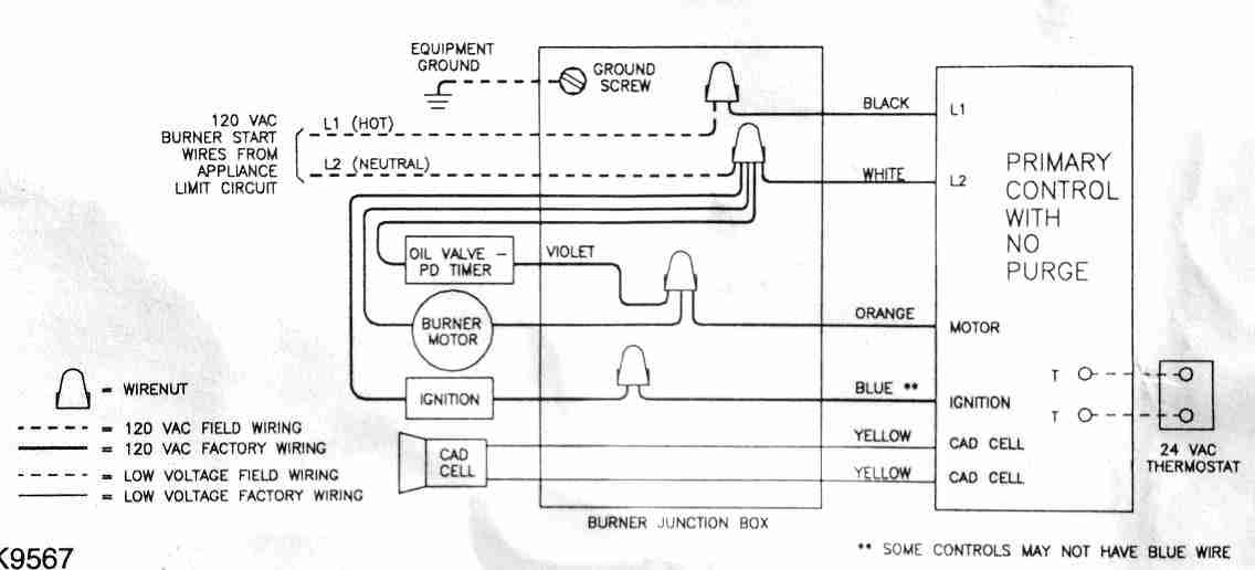
Page 9: Wiring Figure 6 — Typical wiring, R8184G or equivalent primary control Figure 7 — Typical wiring, R7184 primary control (R7184P shown) Instruction Manual - Model AFG Oil Burner Adjust, pipe & wire burner Electrical shock hazard power before servicing. Electrical shock hazard power before servicing. Page 10: Startup & Adjust Burner 3.
24v Wiring Diagram
The Beckett Genisys 7505 is a control system used in oil burners for heating systems. It is designed to provide efficient and reliable operation while also offering advanced diagnostic capabilities. This control system is commonly used in residential and commercial heating systems to ensure optimal performance and energy savings.

Beckett Oil Furnace Wiring Diagram Free Wiring Diagram
Find a Distributor Manuals and Guides A library of product manuals and supplemental guides. Select Manual Category Appliance Guide: CG4 Gas Burner | 80 to 250 MBH | AC Power Dowload Boiler Control Manual: AquaSmart™ 24V Boiler Control | Model 7600 Dowload Burner Manual: ADC Oil Burner | 0.75 to 2.50 GPH | DC Power | 12v Dowload
Beckett Oil Furnace Wiring Diagram
Always follow the appliance manufacturer's published instructions, wiring diagrams and recommendations. *For technical assistance please call 1-800-645-2876 (8:00am - 5:00pm Mon-Fri)*. Do not use in steam applications. For use in hot water boilers or water heaters only.
17+ Beckett Oil Burner Wiring Diagram Images
Typical Furnace Wiring: Figure 6 - 7505A (for replacement of R8184G) Intermittent ignition, no valve-on or motor-off delays SAFETY AND OPERATING LIMITS LIMIT L1 L2 (VLV) VALVE L2 MOTOR L2 (MTR) L2 (IGN) IGNITER CAD CELL MOTOR
