
2.7t Ignition Coil Wiring Diagram
1 2 Ignition System Wiring Diagram. 1997, 1998, 1999 4.6L Ford F150, F250. Coil Pack, Crankshaft Position (CKP) Sensor, Camshaft Position (CMP) Sensor Circuit Diagram.
Harley Davidson Coil Wiring Diagram Cadician's Blog
#1 · Aug 19, 2016 This seems like a very simple and basic thing to know, and yet I cannot seem to find any consistent directions on how to do so, for any vehicle, anywhere online. I am installing a new ignition coil in a 390 fe on a 65 galaxie. Not electronic ignition, just the original replacement old-fashioned $22 coil.
Ignition Coil Wiring Diagram Ford Ignition Coil Wiring Diagram
Like in a conventional ignition system, each ignition coil (in the Ford coil pack) needs a power source and a switching signal to fire off a spark (if you want to read a primer on ignition coils, click here: Automotive Diagnostic Tips And Techniques: The Ignition Coil ).

Model A Ford Ignition Wiring Diagram Wiring Diagram Schemas
Ignition System Wiring Diagram (1994-1995 Ford E150, E250, E350) 1992, 1993 (4.9L, 5.0L, 5.8L, 7.5L) Ford E150, E250 and E350. This fuel pump circuit wiring diagram includes the following circuits: Ignition Coil. Ignition Control Module (ICM). Profile Ignition Pickup (PIP) Sensor.
Model A Coil Wiring Diagram Dapperly
The mesmerizing labyrinth of wires within a Ford ignition coil wiring diagram unravels a secret world of electrical connections. Like an artist's palette, this intricate design holds the key to a perfectly synchronized symphony under the hood. Join us on a journey through these enigmatic lines as we unlock the mysteries of Ford's ignition coil wiring diagram.

Pin on cars
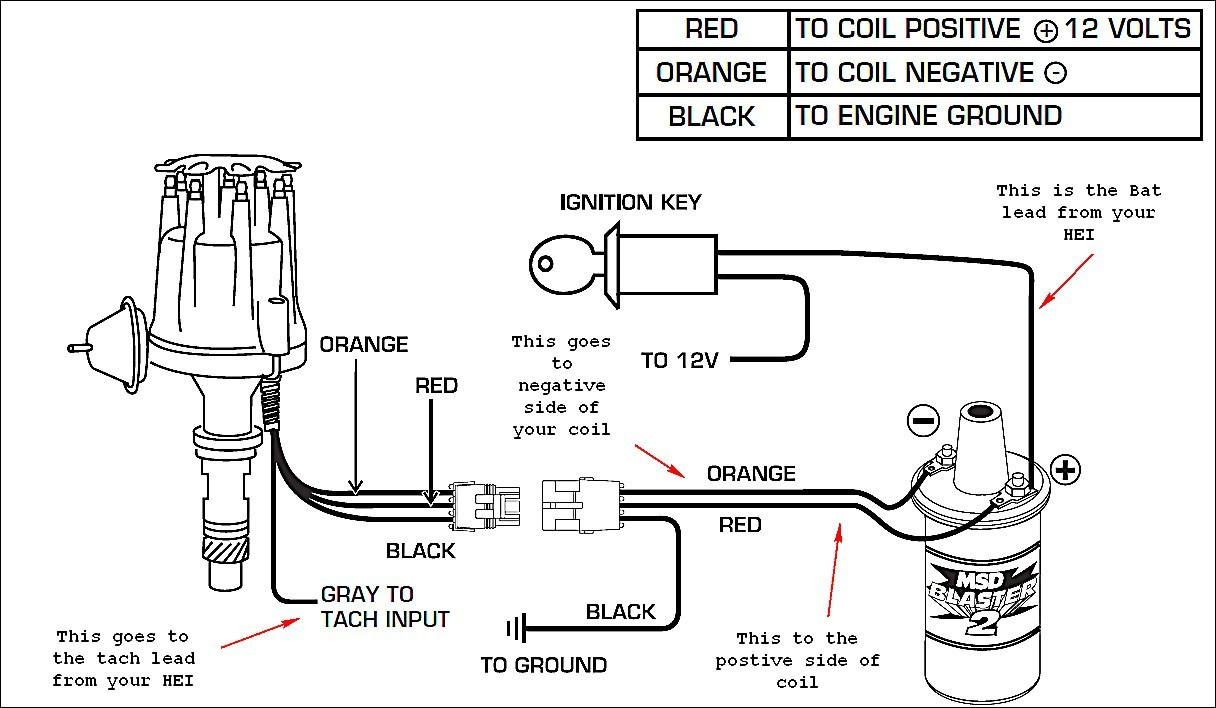
white wire - ign pos. Red wire - coil pos ( no ballast ) green out of the duraspark box to coil negative. the yellow , purple and black to distributor respectively. When I jump the starter solenoid I have ZERO spark out of the coil and the negative side is not switch. I have positive on both sides of the coil.
Ignition Coil Wiring Diagram / Points Condenser Coil Wiring Unique
TYPICAL WIRING DIAGRAM (NO COWL LAMPS) 1928 TO MARCH 1929 TYPICAL WIRING DIAGRAM (WITHOUT COWL LAMPS) beginning in February 1929 About Ford Wiring Wires were cloth covered, rubber insulated Ford used 16 gauge wire on lamp wiring Wire gauges in 1930's not the same as today Wires were bigger around, yet not as good Modern materials
[DIAGRAM] 9n Ford Coil Wiring Diagram FULL Version HD Quality Wiring
The Ford Fiesta ignition coil wiring diagram is essential for any driver who wants to ensure their engine's performance. It helps you identify and troubleshoot electrical problems in the vehicle's electrical system with ease. The diagram also helps you decipher where the individual parts of your engine are located and how they are connected.

[DIAGRAM] Diagram Of Ford Focus Ignition Coil Wiring
Published on: October 27, 2022 4 min read Contents Below, ill cover the 3-wire ignition coil with a diagram of its wiring and some useful information. The purpose of an ignition coil is to produce high voltage for spark plugs. However, the ignition coil pins must be correctly connected to other electrical components.
Ford Ignition Coil Wiring Diagram Collection
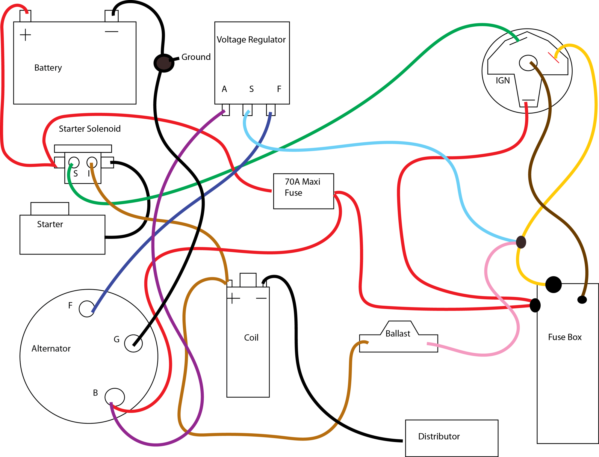
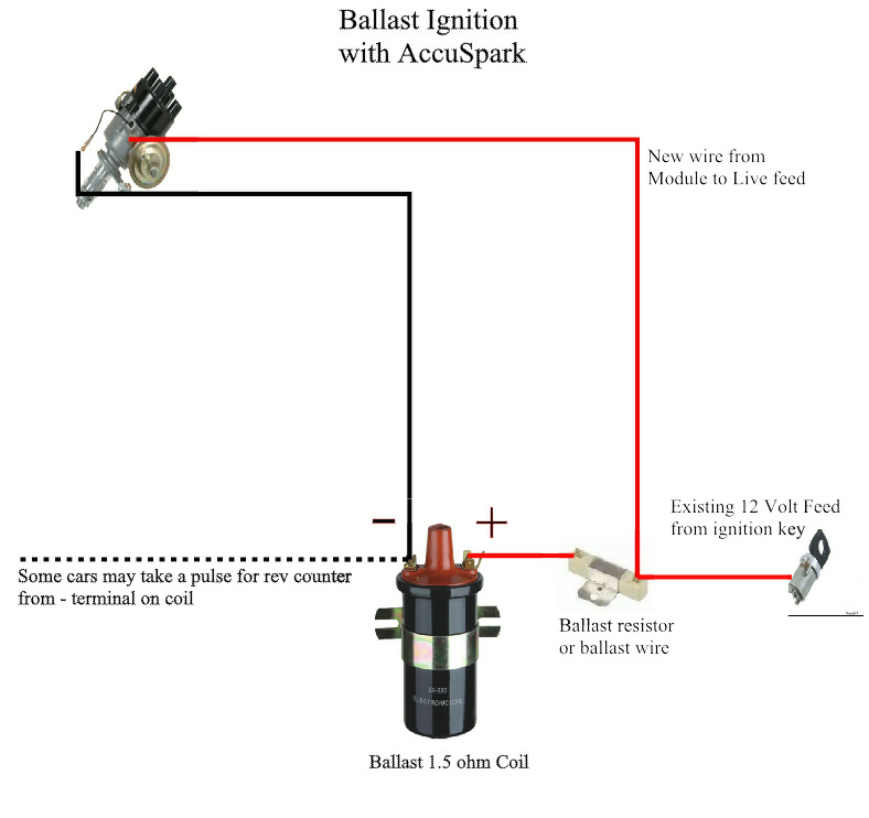
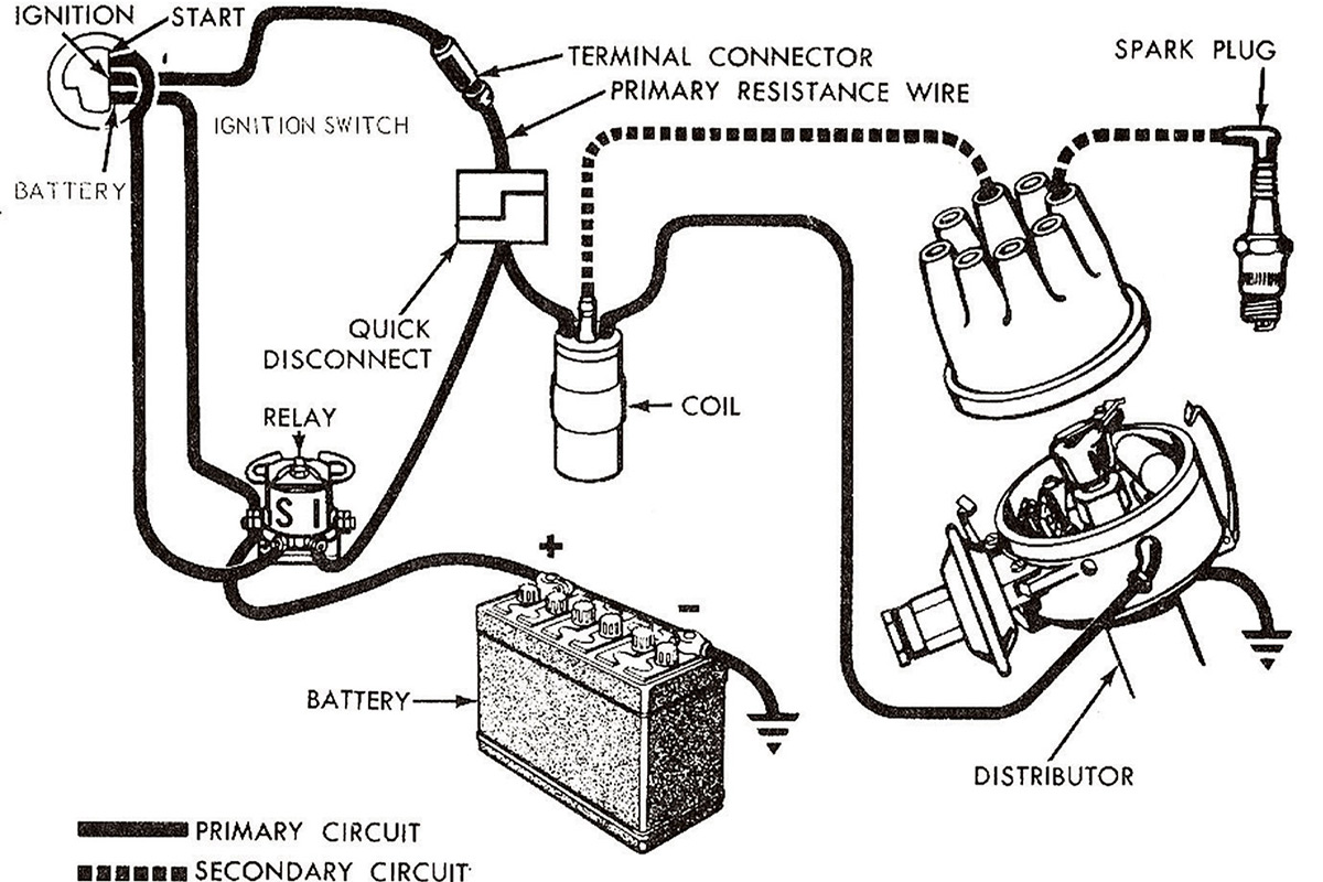
Step 1: Assemble the Components of the Ignition System Video | Okki Moeljadi A conventional ignition system consists of the following components; Battery (mostly 12 volts battery) Ignition switch Resistor Ignition coil Points Rotor Distributor housing Distributor Cap Spark plugs Step 2: Connect the Ignition System to a Battery Video | Okki Moeljadi

[DIAGRAM] Diagram Of Ford Focus Ignition Coil Wiring
# 1 07-22-2019, 01:31 PM Daugust32 Junior User Thread Starter Join Date: Apr 2018 Posts: 79 Likes: 0 Received 1 Like on 1 Post Ignition Coil Wiring Diagram Before I start splitting open electrical tape, can someone post a wiring diagram that includes the ignition switch, ignition coil, and starter solenoid? For reference, this is a 1966 352FE.
Ignition Wiring Diagram Ford Images Wiring Diagram Sample
Ignition Coil Wiring Diagram Ford. In a Ford vehicle, the ignition coil is responsible for generating the electrical spark needed to ignite the air-fuel mixture in the engine. The proper wiring of the ignition coil is crucial to ensure a reliable and efficient ignition process. Let's take a look at the typical wiring diagram for a Ford.
ford points ignition wiring diagram
This simplified ignition system wiring diagram applies to the following vehicles: 1992, 1993 (4.9L, 5.0L, 5.8L, 7.5L) F150, F250, and F350. 1992, 1993 (4.9L, 5.0L, 5.8L) Bronco. The PIP (Profile Ignition Pickup) is the defacto crankshaft position sensor and is located inside the distributor (although in the wiring diagram it's not illustrated.
Ignition Circuit Wiring Wiring Diagram Blog Ford Ignition Coil
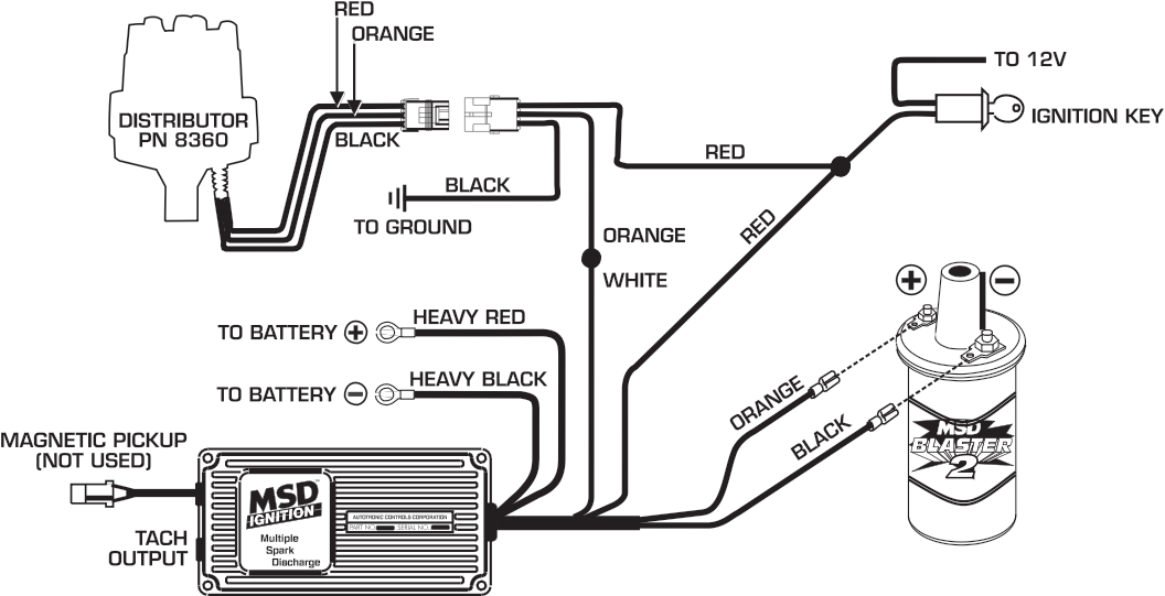
It consists of five wires: one red wire that supplies the power, one yellow wire that grounds the coil pack, one black wire that connects to the negative battery cable, one green wire that feeds the starter, and one white wire that connects to the coil pack.
Ford Ignition Coil Wiring Diagram
The diagram typically shows the distributor, ignition coil, ignition switch, and various wires that connect them. Each terminal is labeled and color-coded to ensure proper connection. The purpose of the points and condenser wiring is to control the flow of electricity and ensure the spark plug fires at the correct time.
22R Ignition Coil Wiring Diagram Distributor Ignition Coil Wiring
This inexpensive spark tester is a MUST have tool to be able to correctly diagnose the Coil-On-Plug ignition coils on your Ford (or Mercury or Lincoln) vehicle with the info/tests in this article (don't have an HEI spark tester? Need to buy one? You can buy it here: OTC 6589 Electronic Ignition Spark Tester ). Battery jump start cables.
